
E-I core transformer 2x 24 V 50 VA
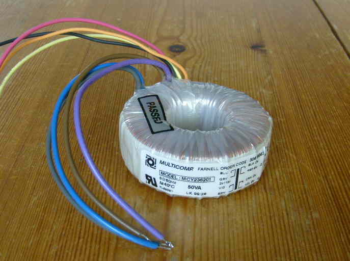
Toroidal transformer 2x 9V 50 VA
Energy losses in transformers, rectifiers and mains adaptors
In this article I describe measurements on transformers, rectifiers and mains
adaptors.
The aim is, to see if energy can be saved by using the correct components.
E-I transformers versus toroidal transformers
First I measured the energy losses in two transformers, both with 50 VA power
rating.
One transformer is a conventional transformer with a E-I core.
The other transformer is one with a toroidal core.
E-I core transformer 2x 24 V 50 VA |
Toroidal transformer 2x 9V 50 VA |
From the transformers, I measured the output voltage at several loads.
The input power of the transformer is measured with my
energymeter .
From this data I calculated output power, power loss, and efficiency of the
transformer
The efficiency is output power divided by input power.
The power loss is the difference between output power and input power, the power
loss is converted into heat in the transformer.
The two transformers have different output voltages, because of that I use for
the two transformers different values of load resistors.
The output windings of the transformers are series connected.
Table 1: Losses in E-I core transformer 2x 24 V 50 VA
| Load resistors parallel |
Output voltage (Volt a.c.) |
Input power (Watt) |
Output power (Watt) |
Efficiency | Power loss (Watt) |
| - | 9.1 | 0.000 | 0.000 | 9.100 | |
| 1x 560 Ω | 51.0 | 18.1 | 4.645 | 0.257 | 13.455 |
| 2x 560 Ω | 50.6 | 21.9 | 9.144 | 0.418 | 12.756 |
| 3x 560 Ω | 50.2 | 25.3 | 13.500 | 0.534 | 11.800 |
| 4x 560 Ω | 49.8 | 28.7 | 17.715 | 0.617 | 10.985 |
| 6x 560 Ω | 49.1 | 35.5 | 25.830 | 0.728 | 9.670 |
| 8x 560 Ω | 48.5 | 42.6 | 33.604 | 0.789 | 8.996 |
| 10x 560 Ω | 47.7 | 49.3 | 40.630 | 0.824 | 8.670 |
Table 2: Losses in toroidal transformer 2x 9 V 50 VA
| Load resistors parallel |
Output voltage (Volt a.c.) |
Input power (Watt) |
Output power (Watt) |
Efficiency | Power loss (Watt) |
| - | 1.16 | 0.000 | 0.000 | 1.160 | |
| 1x 82 Ω | 20.1 | 5.33 | 4.927 | 0.924 | 0.403 |
| 2x 82 Ω | 20.0 | 9.97 | 9.756 | 0.979 | 0.214 |
| 3x 82 Ω | 19.7 | 14.38 | 14.198 | 0.987 | 0.182 |
| 4x 82 Ω | 19.4 | 18.70 | 18.359 | 0.982 | 0.341 |
| 6x 82 Ω | 19.1 | 27.70 | 26.693 | 0.964 | 1.007 |
| 8x 82 Ω | 18.7 | 35.90 | 34.116 | 0.950 | 1.784 |
| 10x 82 Ω | 18.4 | 43.50 | 41.288 | 0.949 | 2.212 |

Graph 1:
Efficiency versus output power
and power loss versus output power.
1 = E-I core transformer (see table 1)
2 = Toroidal transformer (see table 2)
Losses in rectifiers.
The following measurements show the effect of several kinds of rectifiers on
power loss.
Rectifier with 4 silicon diodes
 |
Circuit diagram 1 The toroidal transformer 2x 9V 50 VA is
connected in this way to a rectifier circuit. |
Table 3: Losses in toroidal transformer + 4 silicon diodes,
corresponding to circuit diagram 1.
| Load resistors parallel |
Output voltage (Volt d.c.) |
Input power (Watt) |
Output power (Watt) |
Efficiency | Power loss (Watt) |
| - | 13.46 | 1.17 | 0.000 | 0.000 | 1.170 |
| 1x 47 Ω | 12.26 | 3.98 | 3.198 | 0.804 | 0.782 |
| 2x 47 Ω | 11.84 | 7.22 | 5.965 | 0.826 | 1.255 |
| 3x 47 Ω | 11.53 | 10.15 | 8.486 | 0.836 | 1.664 |
| 4x 47 Ω | 11.28 | 13.14 | 10.829 | 0.824 | 2.311 |
| 6x 47 Ω | 10.80 | 18.67 | 14.890 | 0.798 | 3.780 |
| 8x 47 Ω | 10.40 | 23.41 | 18.410 | 0.786 | 5.000 |
| 10x 47 Ω | 10.03 | 27.95 | 21.404 | 0.766 | 6.546 |
Rectifier with 2 silicon diodes
 |
Circuit diagram 2. The rectifier is now connected in this way, with two silicon diodes (instead
of 4). |
Table 4: Losses in toroidal transformer + 2 silicon diodes, corresponding to circuit diagram 2.
| Load resistors parallel |
Output voltage (Volt d.c.) |
Input power (Watt) |
Output power (Watt) |
Efficiency | Power loss (Watt) |
| - | 13.95 | 1.17 | 0.000 | 0.000 | 1.170 |
| 1x 47 Ω | 12.94 | 4.00 | 3.563 | 0.891 | 0.436 |
| 2x 47 Ω | 12.47 | 7.46 | 6.617 | 0.887 | 0.843 |
| 3x 47 Ω | 12.10 | 10.60 | 9.345 | 0.882 | 1.255 |
| 4x 47 Ω | 11.80 | 13.60 | 11.850 | 0.871 | 1.750 |
| 6x 47 Ω | 11.23 | 19.05 | 16.100 | 0.845 | 2.950 |
| 8x 47 Ω | 10.78 | 23.86 | 19.780 | 0.829 | 4.080 |
| 10x 47 Ω | 10.30 | 28.06 | 22.572 | 0.804 | 5.488 |
Rectifier with 2 schottky diodes
|
Circuit diagram 3 Now the 2 silicon diodes are replaced by 2 schottky diodes, type MBR360 (3A 60V). The transformer is the same 2x 9V 50 VA toroidal. The value of the elco is 4700 μF. |
Table 5: Losses in toroidal transformer + 2 schottky diodes, corresponding to circuit diagram 3
| Load resistors parallel |
Output voltage (Volt d.c.) |
Input power (Watt) |
Output power (Watt) |
Efficiency | Power loss (Watt) |
| - | 14.22 | 1.17 | 0.000 | 0.000 | 1.170 |
| 1x 47 Ω | 13.30 | 4.20 | 3.764 | 0.896 | 0.436 |
| 2x 47 Ω | 12.79 | 7.69 | 6.961 | 0.905 | 0.729 |
| 3x 47 Ω | 12.43 | 10.86 | 9.862 | 0.908 | 0.998 |
| 4x 47 Ω | 12.10 | 14.06 | 12.460 | 0.886 | 1.600 |
| 6x 47 Ω | 11.48 | 19.51 | 16.824 | 0.862 | 2.686 |
| 8x 47 Ω | 11.00 | 24.32 | 20.596 | 0.847 | 3.724 |
| 10x 47 Ω | 10.57 | 28.80 | 23.771 | 0.825 | 5.029 |
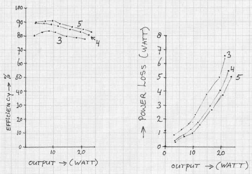 |
Graph 2: The values for efficiency and power loss from table 3, 4 and 5 are shown in these graphs. The use of 2 schottky diodes gives the best efficiency, and the lowest power loss. |
Losses in several kinds of power supplies and mains adaptors
Toroidal 2x 6V 15 VA

I have build this power supply with the following components:
1 toroidal transformer 2x 6V 15 VA
2 schottky diodes MBR360 and an elco of 4700 μF.
The output voltage is not stabilized.
Table 6: Toroidal transformer 2x 6V 15 VA
| Load resistors parallel |
Output voltage (Volt d.c.) |
Input power (Watt) |
Output power (Watt) |
Efficiency | Power loss (Watt) |
| - | 9.48 | < 0.50* | 0.000 | 0.000 | < 0.500 |
| 1x 82 Ω | 8.95 | 1.18 | 0.977 | 0.828 | 0.203 |
| 2x 82 Ω | 8.65 | 2.11 | 1.825 | 0.865 | 0.285 |
| 3x 82 Ω | 8.41 | 3.05 | 2.588 | 0.848 | 0.462 |
| 4x 82 Ω | 8.20 | 3.98 | 3.280 | 0.824 | 0.700 |
| 5x 82 Ω | 8.01 | 4.63 | 3.912 | 0.845 | 0.718 |
| 6x 82 Ω | 7.84 | 5.56 | 4.497 | 0.809 | 1.063 |
| 8x 82 Ω | 7.50 | 6.94 | 5.488 | 0.791 | 1.452 |
| 10x 82 Ω | 7.23 | 8.07 | 6.375 | 0.790 | 1.695 |
* My energy meter cannot measure power below 0.5 W.
Switch mode mains adaptor.
 |
Switch mode mains adaptor Brand: HQ Model: P.SUP.SMP1-BL This adaptor
is adjustable between 3 and 12 Vdc. This adaptor is tested at 9 volt output voltage. |
Table 7: switch mode mains adaptor
| Load resistors parallel |
Output voltage (Volt d.c.) |
Input power (Watt) |
Output power (Watt) |
Efficiency | Power loss (Watt) |
| - | 9.06 | < 0.50 | 0.000 | 0.000 | < 0.500 |
| 1x 82 Ω | 9.05 | 1.87 | 0.999 | 0.534 | 0.871 |
| 2x 82 Ω | 9.04 | 3.01 | 1.993 | 0.662 | 1.017 |
| 3x 82 Ω | 9.02 | 4.40 | 2.977 | 0.677 | 1.423 |
| 4x 82 Ω | 9.00 | 5.56 | 3.951 | 0.711 | 1.609 |
| 5x 82 Ω | 8.98 | 6.72 | 4.917 | 0.732 | 1.803 |
| 6x 82 Ω | 8.97 | 8.14 | 5.887 | 0.723 | 2.253 |
| 7x 82 Ω | 8.95 | 9.30 | 6.838 | 0.735 | 2.462 |
Non stabilized mains adaptor
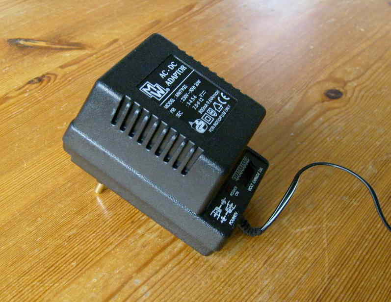 |
Non stabilized mains adaptor. Brand: MW Model: MW79GS The output voltage is adjustable between 3 and 12 V, and
tested at 9V. The adaptor has internal a small E-I core transformer. |
Table 8: non stabilized mains adaptor 800 mA
| Load resistors parallel |
Output voltage (Volt d.c.) |
Input power (Watt) |
Output power (Watt) |
Efficiency | Power loss (Watt) |
| - | 12,42 | 2,22 | 0,000 | 0,000 | 2,220 |
| 1x 82 Ω | 11,56 | 6,68 | 1,630 | 0,244 | 5,050 |
| 2x 82 Ω | 10,99 | 7,58 | 2,946 | 0,389 | 4,634 |
| 3x 82 Ω | 10,50 | 8,25 | 4,034 | 0,489 | 4,216 |
| 4x 82 Ω | 10,08 | 8,97 | 4,956 | 0,553 | 4,014 |
| 5x 82 Ω | 9,74 | 9,63 | 5,785 | 0,601 | 3,845 |
| 6x 82 Ω | 9,40 | 10,21 | 6,465 | 0,633 | 3,745 |
Stabilized mains adaptor
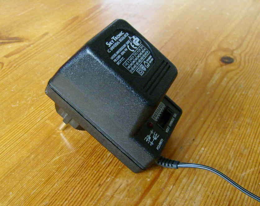 |
Stabilized mains adaptor. Brand: Skytronic Model: MW300GS The output voltage is adjustable between 1.5 and 12 V,
and tested at 9V. |
Table 9: stabilized mains adaptor
| Load resistors parallel |
Output voltage (Volt d.c.) |
Input power (Watt) |
Output power (Watt) |
Efficiency | Power loss (Watt) |
| - | 9.40 | 1.60 | 0.000 | 0.000 | 1.600 |
| 1x 82 Ω | 9.35 | 6.44 | 1.066 | 0.166 | 5.374 |
| 2x 82 Ω | 9.32 | 6.82 | 2.119 | 0.311 | 4.701 |
| 3x 82 Ω | 9.29 | 7.93 | 3.157 | 0.398 | 4.773 |
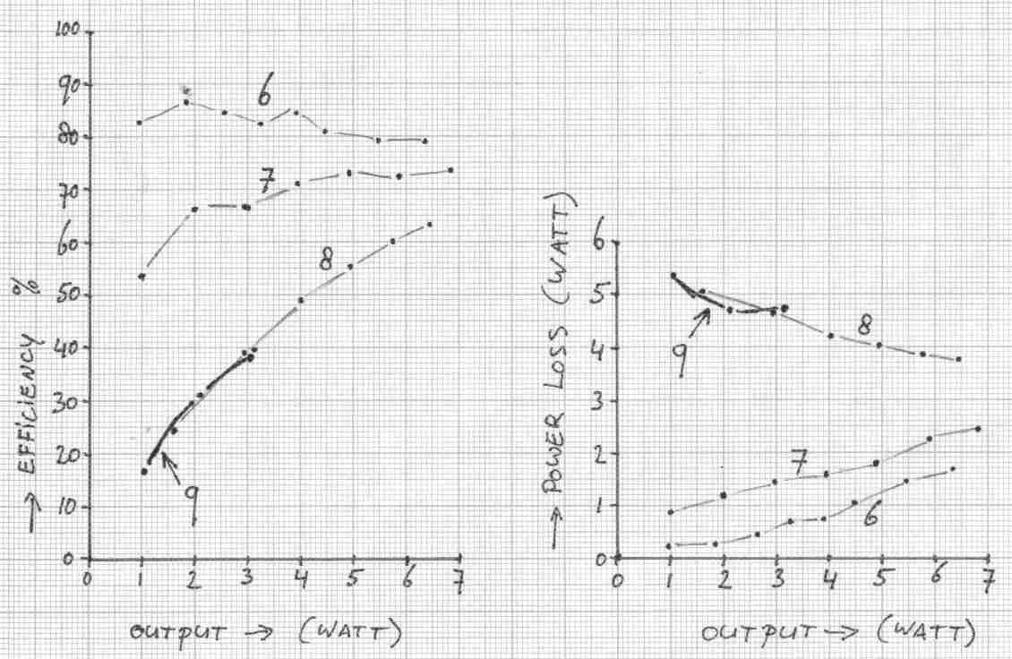
Graph 3:
Efficiency en power loss for:
6 = Power supply with toroidal transformer (see table 6)
7 = Switch mode mains adaptor (see table 7)
8 = Non stabilized mains adaptor (see table 8)
9 = Stabilized mains adaptor (see table 9)
Conclusion:
By using toroidal transformers, energy can be saved in power supplies.
Especially at low output current, the toroidal transformer is much better then
the E-I core transformer.
Also by using schottky diodes and rectifiers with 2 diodes (instead of 4),
energy can be saved.
Every reduction of losses, can save at long term quite
some energy.
Every Watt saving, gives per year a saving of 8.76 kWh.