Noise measurements of several NPN transistors. (For
PNP transistors, see part5
)
On this page, the noise performance of several NPN transistors is tested.
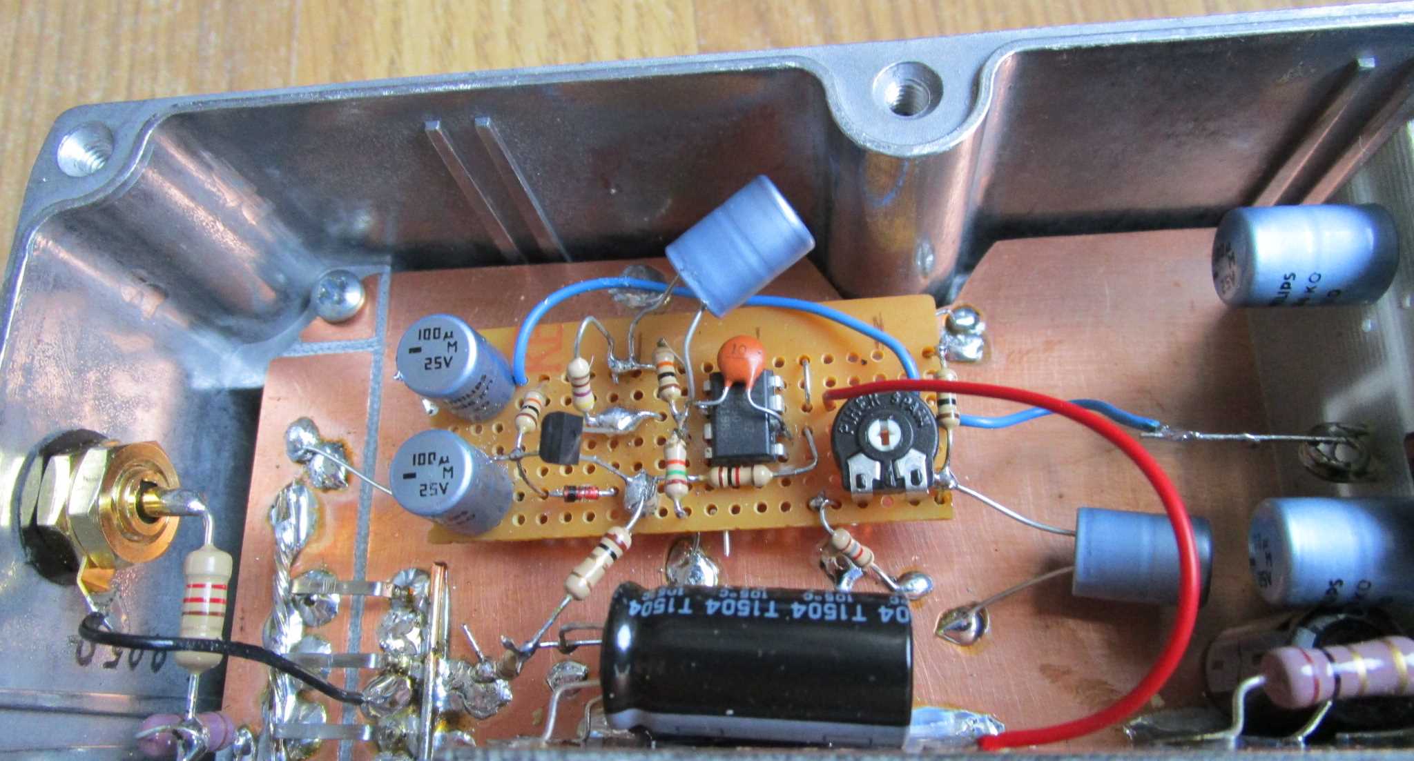
Figure 1, this is the amplifier I use for measuring the noise of a
transistor.
T1 is the transistor under test, the transistor works with 10 mA collector
current.
For other collector currents, R7 and R2 must be changed.
With potentiometer R4, the output of the op-amp can be adjusted to about 6 volt.
R10 and C7 are added to prevent oscillation of the amplifier.
Diode D1 protects the transistor base-emitter junction for too high reverse voltage.
The gain of the circuit is about 1000 times (60 dB), determined by R11, R1 and
the ESR (series resistance) of C5 and C6.
The output goes to another 60 dB amplifier in the test setup, and then
to a spectrum analyser, as described in
part 1.
The input signal of (exact !) -140 dBV, is thus amplified about 120 dB and
reaches the spectrum analyser at a level of about -20 dBV.
The level of the input noise floor is measured with regard to the 1 kHz -140 dBV
test tone.
Figure 2, the amplifier for measuring the transistor noise.
Transistor type
Manufacturer
View datasheet
of transistor
hfe
at 25°C
Ic=10 mA
Measured input noise
of test amplifier
at 1 kHz, Ic =10 mA.
nV/√Hz
Calculated transistor
base resistance
Rbb
(Ω)
Calculated Input noise
of only the transistor.
(R_circuit = 0Ω)
at 1 kHz, Ic=10 mA.
nV/√Hz
This table gives an overview of the transistors tested, with the measured input voltage
noise of the test amplifier, and the calculated base resistance Rbb of the
transistors.
Also the voltage noise of only the transistor is calculated at 10 mA collector
current.
For an explanation of the Rbb value, see
part 4 .
For more info about the testing method, see
part 1 and
part 2 .
The collector current of the transistors is in all cases 10 mA.
For the BD139, the Rbb could not be determined, because the spectrum is not
flat, so over the entire spectrum we have influence of 1/f noise, and / or
current noise building up a non-flat noise across input capacitor C1.
For all other transistors, the Rbb value was determined from the noise at 1 kHz.
In the next figure, the input noise voltages of all measured transistors are plotted in
one diagram.
Figure 3, input noise voltage of the test setup, with different input transistors.
Also the AD797A low noise op-amp is added for comparison.
For this diagram, I compensated the values for the frequency response of the
test setup.
Figure 4 shows the test setup response, and the compensation I applied for
making figure 3.
Figure 4, frequency response of test setup, and the compensation curve.
Figure 5, noise spectrum of AD797A amplifier version 4, as described in
part 2 .
The AD797A is one of the lowest (voltage) noise op-amps available.
Figure 6, noise spectrum of the test amplifier with a ZTX851 transistor at 10 mA collector current.
Compared to the AD797A, this transistor amplifier has much lower noise.
For the test setup with the ZTX851 transistor at 10 mA, two sound files are
recorded.
The first is a 1000 Hz test tone at -140 dBV, the first 10 seconds the tone is
on, the last 5 seconds it is off. ZTX851_10mA_1000Hz_-140dBV.mp3
The second recording contains music with an average level of -143 dBV (0.07
μV) at the amplifier input. ZTX851_10mA_music_-143dBV.mp3
For a good comparison, the recordings are made with the same input levels and
content as with the AD797A amplifier, which you can find at the bottom of
part 2
.
As you see in the picture of the noise spectrum of the ZTX851, there is some hum
visible above the noise floor.
I applied a 80 Hz high pass filter on the audio files, to remove at least the
strongest component (50 Hz) which was very annoying in my speakers.
Figure 7, here the ZTX851 is again tested at 10 mA, just like in figure 6,
but the input capacitor of the test amplifier (C1) is changed from 100
μF electrolytic to 100 μF plastic film capacitor.
The electrolytic capacitor has an ESR (series resistance) of about 0.5 Ω,
while the
plastic film capacitor has an ESR of probably below 0.01 Ω
This causes the noise floor to be about 0.5 dB lower.
But the 100 μF film capacitor is so large, that I can't place the metal lid on
the test setup anymore.
This causes the level of 50 Hz (+ harmonics) interference to increase
considerably, the situation got better when I wrapped some aluminium foil around
the test setup, which shielded most of the interference.
But anyhow, if you ignore the 50 Hz harmonics, you see the noise floor at 1 kHz
is about 0.5 dB lower then in figure 6.
By the way, the interference near 20 kHz comes from my computer and / or
monitor.
Figure 8, a large 100 μF film capacitor at
the input of the test amplifier.
Once I read on the internet, that you can ruin the noise performance of a
transistor, by putting a reverse current trough the base-emitter junction.
I have tested this with the ZTX851 transistor which is tested above.
A 12 volt supply was connected with the minus to the base, and the plus via a 1
kΩ resistor to the emitter.
That gives about 4 mA reverse current, this means the b-e junction comes in
reverse conduction (like a zenerdiode) at -8 volt.
I let the current flow for 10 seconds, then put the transistor back in the test
setup, and tested the transistor noise once again.
But the noise was exactly the same as before.