Oscillator with super low supply voltage
This article describes the development of a oscillator with a very low supply
voltage.
Just to see how low we can go, and if possible let the oscillator run on the
voltage generated by a thermocouple in a candle flame.
 |
Before making the oscillator we first need a very low voltage power
supply. A normal power supply can't accurate be set to a very low
output voltage. |
Version 1
 |
This is the first oscillator build. It uses 2 components: |
The transformer is model 952.431 made by Adastra.
The high impedance winding is 80 kΩ, and the low
impedance winding is 8 or 16 Ω.
When using the 8 Ω winding, the voltage ratio between the windings is √(80.000 /
8) = 100
So the (ac) voltage at the drain of the FET, is amplified 100 times when it
reaches the gate of the FET.
The voltage gain of the FET only needs to be 0.01 to keep the oscillations
going.
This low voltage gain can already be reached with very low supply voltages.
A junction FET is used because these FET's
already conduct at zero gate voltage (Vgs= 0V).
Other active elements like transistors or most MOSFET's need a certain voltage at the
input before they start conducting.
And we don't have such a voltage when the oscillator is powered from a super low
supply voltage.
3 types of junction FET's are tested, the minimum supply voltages needed to start the oscillator are given in the next table
| FET type | Supply voltage |
| BF256B | 57 mV |
| BF256C | 67 mV |
| J310 | 33 mV |
From this first test, I concluded, the J310 FET was the best to use.
Version 2

In this circuit I connected two J310 Fet's in parallel this gives more gain to the
circuit (and also gives more power consumption).
Because of the higher gain the supply voltage can be reduced.
| FET type | Supply voltage |
| 2x J310 |
27 mV |
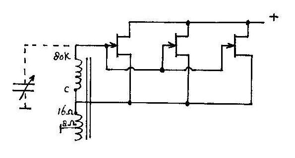
Version 3

Now instead of using the common and 8 Ω
connection on the transformer, I use the winding between 16 Ω and 8 Ω.
This winding has less turns, so the voltage gain of the transformer increases
(from 100 to 244 times).
The circuit is tested with 2 and 3 FET's parallel.
The results are:
| FET type | Supply voltage | Supply current |
| 2x J310 | 19 mV | 1.04 mA |
| 3x J310 | 17 mV | 1.40 mA |
version 4
In this oscillator the low impedance winding is connected to the source (and
not the drain) of
the FET.
The performance is the same as version 3 of the oscillator.
With 3 FET's oscillation starts at 17 mV supply voltage, and 1.4 mA supply
current.
The frequency of oscillation is determined by the inductance of the high
impedance winding, and it's internal capacitance.
The oscillating frequency is about 1200 Hz.
With a variable capacitor across the coils, the frequency can be reduced.
With a 1000 pF variable capacitor, the frequency can be tuned from 1200 to 600
Hz.
Version 5

This oscillator uses 2 transformers.
The low impedance windings are parallel connected.
The high impedance windings are series connected.
The oscillator starts to oscillate at the following supply voltages
| FET type | Supply voltage | Supply current |
| 2x J310 | 17.3 mV | |
| 3x J310 | 12.9 mV | 1.28 mA |
| 4x J310 | 11.7 mV | 1.6 mA |
| 5x J310 | 10.6 mV | 2.0 mA |
The oscillating frequency is 800 Hz
I also tested this circuit with 3 transformers, and 5 parallel FET's
It started with 10.4 mV at 2.15 mA, so not much profit compared to the 2
transformer version.
Version 6
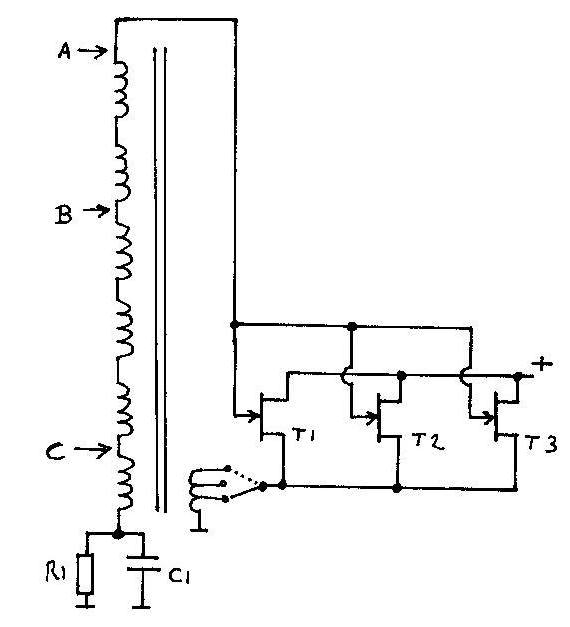
This oscillator uses a self made transformer, described on my webpage
http://www.crystal-radio.eu/transformer_unit2/entrafounit2.htm
In the circuit above, the schematic of the transformer is drawn simplified.
The high impedance winding consists of 6 coils in series.
The low impedance coil can be switched in 3 positions:
- Low number of turns, in this position the impedance of the
high impedance winding is 4 MΩ
- Higher number of turns, in this position the impedance of the
high impedance winding is 2.5 MΩ
- Highest number of turns, in this position the impedance of
the high impedance winding is 1.5 MΩ
|
These measurements are done with 5 FET's
parallel (type: J310). And the gates of the FET's connected to point A (like in the circuit diagram). So using all 6 coils of the high impedance winding. |
|
In these measurements, the gates of the FET's are connected to point B. So using 4 coils of the high impedance winding. In this situation we need more supply voltage. |
From these measurements I found, the supply voltage is the lowest when:
- The low impedance winding is switched in the position "4 MΩ"
- All 6 coils of the high impedance windings are used
In this situation the voltage gain of the transformer is the highest.
|
In the next measurements the number of FET's is
reduced. The gate of the FET's is connected to point A. The oscillating frequency is about 800 Hz |
Until now I measured the oscillation by
connecting a 1:10 oscilloscope probe (10 MΩ) to the gate of the FET's
But this gives some loading on the top of the resonance circuit.
To reduce the loading, I connected the probe to point C, so much lower on the
high impedance winding.
The gates of the FET's are still connected to point A.
With 3 FET's in the oscillator, it started to oscillate at 5.5 mV supply
voltage, and 0.41 mA current.
At this point I stopped the development of the low voltage oscillator.
 |
Oscillator running on 5.5 mV supply voltage. Horizontal: 1 ms
/div. Measured at point: C |
 |
Supply voltage is 10 mV. Horizontal: 1 ms /div. Vertical: 500 mV /div. The wave gets distorted, and frequency
reduces. |
 |
Supply voltage is 20 mV. Horizontal: 1 ms /div. Vertical: 1 Volt /div. DC voltage at the gate of the FET's is now -2.31 Volt.
|
Oscillator powered by a thermocouple.
The oscillator described above (version 6) is now connected to a
thermocouple.
The thermocouple is one as used in gas heaters.
The thermocouple used gives about 13 mV when heated by my soldering iron (370
°C).
In or just above a candle flame, the output is about 20 mV
In a gas flame, the output is about 40 mV, and the thermocouple is then red hot.
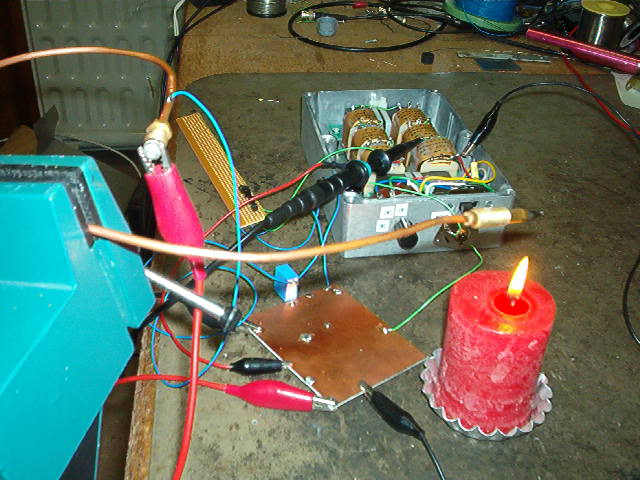
The pictures below show the test set-up of the oscillator, and the
thermocouple above the candle flame.
The oscillator is running very well on this "power supply"