With this coil calculator you can design and calculate the properties of a coil
or transformer.
Enter the parameters in the yellow coloured fields, and
then click the calculate buttons.
Below the calculator you will find more explanation about the calculations. Use the decimal point (not the comma) if
you want to enter decimals.
The inductance of a coil is the property which describes the relation
between the voltage induced in a coil, and the change of current through the coil.
L = VL / (di/dt)
Where:
L = the inductance of the coil in Henry (H).
VL = Voltage induced in the coil in Volt
di/dt = change of current through the coil in Ampere per second.
The magnetic flux, commonly denoted as Φ, is
measured in the unit Weber (Wb).
If you have a loop of wire, and apply 1 Volt to the loop during 1 second, the magnetic
flux in the loop will change by 1 Weber.
It doesn't matter what the size or shape of the loop is, or what material inside
the loop is.
You can imagine the unit Wb as being the number of magnetic field lines through the
loop.
For a single loop applies:
Φ = V.t
If a coil has more then one turn, we can use the following formula:
Φ = V.t / N
Where:
Φ = change of magnetic flux in the coil in Weber
V = voltage across the coil in Volt
t = time in second
N = number of turns of the coil
Magnetic materials as used in coil and transformer cores may be used up to a
certain maximum magnetic flux density.
For low frequency applications (inclusive DC) the maximum flux density is limited by magnetic
saturation of the core material, this flux density is called: Bsat.
When saturated, all magnetic areas in the material are pointing in the same
direction.
It is however in theory possible to increase the flux density above saturation,
because of the permeability of vacuum.
But this requires a lot of current through the coil, and excessive power loss in
the windings.
Above saturation, the coil will lose most of it's inductance, and will start
acting like a coil with no coil material in it.
So, keep the flux density below Bsat.
The value of Bsat is given in the datasheet of the core material.
For instance Bsat is about 0.3 T for ferrite material and about 1.3 T for
silicon steel.
The value of Bsat is depending on temperature, the higher the temperature, the
lower Bsat is in most cases.
In this calculator I use the Bsat value at 100 °C,
which automatically appears in the field Bmax, when you select a core material.
So, this is the most safe value, at lower temperature however Bsat might be
higher.
Maximum magnetic flux density
at higher frequency: Bmax < Bsat
For higher frequency applications the maximum flux
density in the core is limited by the power loss in the core rather then by core
saturation.
At higher frequencies, we need to reduce the value of Bmax below the
Bsat value, in order to avoid overheating the core by it's own power loss.
The higher the frequency, the lower the value of Bmax.
For larger cores, the flux density Bmax must be kept
lower then for smaller cores, to avoid overheating the core.
This is because the volume of the core (which produces the heat) increases
faster then the outside area of the core (which must dissipate the heat).
My coil and transformer calculator doesn't calculate for you the core losses.
Instead, you have to enter a certain maximum flux density in the calculator,
which will keep the core loss below the level you want.
Core loss in silicon steel cores
The next figures show some examples of core loss in silicon steel (also
called: electrical steel or transformer steel).
Figure 1, Core loss in silicon steel.
Figure 1 gives some examples of core loss at different lamination thicknesses
and frequencies.
Higher frequencies gives higher losses.
And thicker lamination gives higher losses.
To convert the lamination thickness from "mil" to "mm" , multiply by 0.0254.
However the core loss (in Watt / kg) is higher at higher frequencies, the
transformer core can be made smaller at higher frequencies.
And you may end up with a high frequency transformer with lower core loss (in Watt),
compared to a low frequency transformer of the same power rating.
For power line transformers, at 50 or 60 Hz, the core loss is usually much
lower then the loss in the windings at full load.
At 50 or 60 Hz you can use in your transformer design, a flux density in the
core equal to: Bsat.
For an audio transformer, you design for the lowest frequency in your audio
signal, as long as this is not more then about 100 Hz, you can use Bsat as the
maximum flux density in the core.
For higher audio frequencies, the magnetizing current and flux density in the
core automatically reduces.
Figure 2, core losses in silicon steel at various frequencies.
This data is for M-19 grade non oriented silicon steel, with 14 mil or
0.36 mm thickness.
Oh, and 1 Lb is equal to 0.45359 kg.
Core loss in ferrite cores
Ferrite cores have much lower power loss at high frequencies then silicon
steel cores.
Information about the maximum flux density at certain frequency can be
found in the datasheet of the ferrite material, here are two examples:
Figure 3, Core loss of ferrite N27.
Figure 3 shows the relation between frequency, flux density and power loss in
the core for ferrite material N27, which saturates at 0.41 T at 100
°C.
Let's suppose we want a maximum power loss in the core of 100 kW/m³
, which is the same as 100 mW/cm³, I indicated this value with the red line.
For a signal of 10 kHz (the green line), we find a maximum peak value for the
flux of 300 mT ( = 0.3 Tesla) at 100 °C.
And for 200 kHz (the blue line), we find a maximum of 50 mT ( = 0.05 Tesla).
Figure 4, Core loss of ferrite 3C90.
Figure 4 shows the core loss for ferrite material 3C90, here the data is
presented slightly different.
For a core loss of 100 kW/m³ ( = 100 mW/cm³), we
find at 200 kHz a maximum peak flux density of 70 mT ( = 0.07 Tesla).
The effective cross section area of a core can be found in the
datasheet of the core, this is the preferred method.
Or you can measure it.
But only magnetic material is part of the effective cross section area, so not
any insulating coating which may cover the core.
Figure 5: In an EI transformer core, the effective cross section area (Ae),
is the area of the centre leg.
Both outer legs will normally have an area of 1/2 Ae.
When you have stacked several cores, the total effective cross section area
Ae(total), is equal to the Ae value of one core, multiplied by the number of
cores
The maximum magnetic flux in the core is calculated with:
Φmax = Bmax . Ae(total)
Where:
Φmax = maximum magnetic flux in the core in Weber
Bmax = maximum magnetic flux density in the core in Tesla
Ae(total) = Total effective cross section area of the core in square metre
The relative permeability
μr of a core
material indicates how much more inductance your coil will have, relative to a
coil with vacuum in the core.
Vacuum has a permeability (μ0)
of about 1.2566 . 10-6 H/m (Henry per metre).
The relative permeability has no unit.
Air has a μr value of 1.00000037 so
practically equal to vacuum.
The relative permeability μr of a core material often
depends on the magnetic flux density in the core.
In this calculator I use the μr value at nearly zero
flux density, in datasheets this is indicated with μi
(relative initial permeability).
Another parameter you can find in datasheets is: μa
(relative amplitude permeability), which is the μr value
at higher flux density.
If you have a coil wound on a ring core, the core consists completely of core
material, and is perfectly closed..
The effective permeability is then equal to the relative permeability of the
core material.
But a lot of cores consist of two parts, which are put together around a coil
former with the windings on it.
The two core parts will always have here and there some spacing or air gap in
between, which seems to reduce the permeability of the core.
You then have a core with a effective permeability which is smaller then the
relative permeability of the core material.
Sometimes an air gap is intentionally made in the core, to reduce the
effective permeability.
By doing this, the maximum current through the coil increases, but not the flux
density in the core.
It gives the same effect as using another core material with lower permeability.
The effective permeability of a core with air gap is:
μe = μr . le / (le +(g .μr))
Where:
μe = effective permeability of the core.
μr = relative permeability of the core material.
le = effective length of the magnetic path in the core
g = length of the air gap (measured in same unit as le)
The effective length of the magnetic path in the core can be found in the
datasheet of the core.
Or you can estimate it from the dimensions of the core.
It is the length that a magnetic field line in the centre of the core material
would travel.
Do not include any air gap in this path length, but only the path in the core
material itself.
An air gap is an layer of air in the magnetic path of the core.
Figure 6: air gap in the centre leg of an EI transformer core.
Figure 6 shows an air gap caused by the centre transformer leg being shorter
then the two outer legs.
The dashed lines indicate the magnetic field lines, with a length of: le
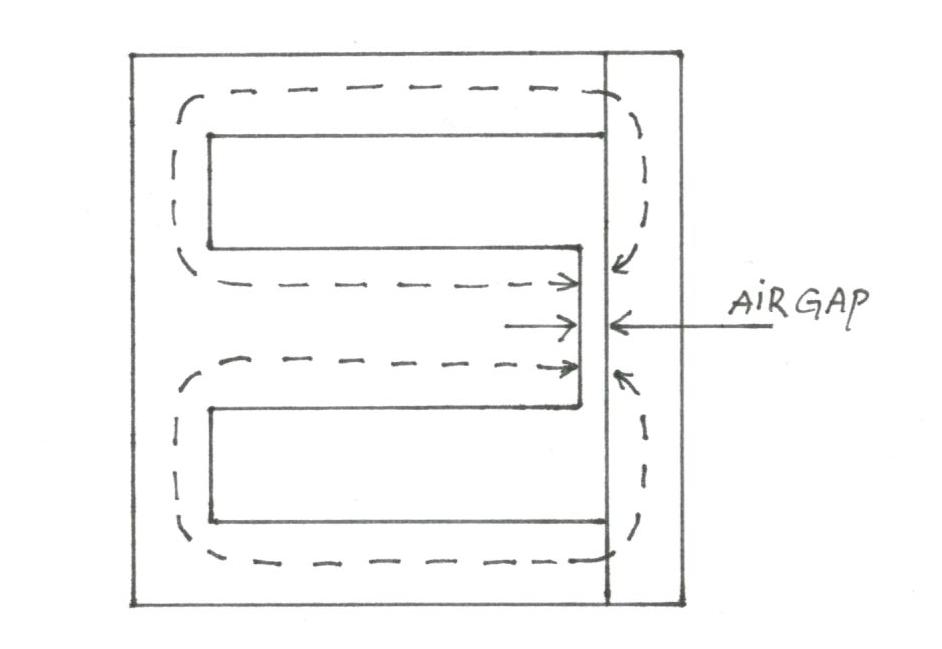
Figure 7: air gap in all the legs of an EI transformer core.
Figure 7 is another EI transformer core with an air gap.
Here, all transformer legs have the same length, and the air gap is created by
pulling the "E" and "I" part slightly apart.
You see, the field lines now have to jump two times across an air layer to form
a closed loop.
This means we have to calculate with an air gap which is twice the distance
between the "E" and "I" part.
The air gap doesn't necessarily be filled with air, other non magnetic materials
like paper or plastic are also useful.
In transformers, an air gap in the core will cause lower coupling between the
windings, which may be undesired.
The inductance factor AL of a core, is the
inductance of one winding around this core.
When you have more then one winding, the inductance of the coil will be:
L = N² . AL
Where:
L = Inductance of the coil
N = Number of turns
AL = Inductance factor of the core
If you don't know the AL factor of a core, it can be
calculated from the effective permeability and the core dimensions:
AL = μ0 . μe . Ae(total) /
le
Where:
AL = inductance factor in H/N²
μ0 = permeability of vacuum = 1.2566 . 10-6 H/m
μe = effective permeability of the core
Ae(total) = Total effective cross section area of the core in m²
le = effective length of the magnetic path in the core in m.
Stacking cores means, using more then one core, and let the windings go through all of
these cores.
Compared to a coil with one core, the inductance is multiplied by the number of
cores stacked.
The wire which you use to wind a coil or transformer will have some resistance.
This resistance is calculated with:
R = ρ . l / A
Where:
R = resistance of the wire
ρ = the resistivity of the wire material in Ω.m, for copper this is about
1.75 . 10-8 Ω.m
l = length of the wire in metre
A = cross section area of the wire in square metre
The calculated value for the copper area, is as it says only the copper of the
windings.
In practice you also have to do with wire insulation, air between the turns
and probably a coil former.
So, in practice you need more space for the winding, let's say 2.5 or 3 times
the calculated value for the copper.
Maximum current through the coil, is the current that gives the maximum
allowable magnetic flux in the core.
Imax = Φmax . N /L
Where:
Imax = maximum current through the coil (DC or AC peak)
Φmax = The maximum magnetic flux in the core in Weber
N = The number of turns
L = Inductance of the coil in Henry
When you connect a coil to a DC voltage supply V, the current I will increase with
time.
In other words, you are charging the coil.
As long as the coil has no resistance, the current increases linearly, and the
time for reaching a certain current is given by:
t = L.I / V
If the coil has resistance, the current increase is no longer linear.
The maximum current through the coil is limited to a value of: I=V/R.
The charging time for a coil with resistance is calculated with:
t = -L/R . LN(1-(I.R/V))
Where:
t = time in seconds to increase the current from zero to the value I.
L = Inductance of the coil in Henry.
R = Resistance of the coil in Ohm.
LN = Natural logarithm.
I = Current in Ampere for which you calculate the charging time.
V = Voltage across the coil.
In this calculator, the time is calculated, to charge up to the maximum coil
current, so to the current that gives a flux density of Bmax in the core.
The maximum AC voltage (sine wave) which you may put across the coil is
calculated with:
Vmax = 4.44 . Φmax . N . f
Where:
Vmax = the maximum sine wave AC voltage across the coil in Volt RMS
Φmax = maximum magnetic flux in the core in Weber
N = number of turns on the coil
f = frequency of the voltage in Hertz
The factor 4.44 is a multiplication of two
factors, which are:
4 , the flux varies between zero and +Φmax in 1/4 cycle, the next 1/4 cycle
it returns back to zero, the next two 1/4 cycles to -Φmax and back to
zero.
So in one cycle, the flux changes over a total of 4 times Φmax.
Multiplied by:
1.11 , this is the form factor of a sine wave, which is the ratio of the RMS value to
the average value.
Here is another way of calculating the maximum AC voltage across the coil:
Vmax = Imax . 2. pi . f .L / √2
Here we multiply the maximum current through the coil by the coil impedance at
frequency f, and then divide by √2 to convert peak value to RMS value.
From the formula for maximum voltage across a coil (see above), we can easily
find the formula for the number of turns for the primary transformer winding.
Np = Vp / (4.44 . Φmax . f) This formula is for sine wave
voltages.
Where:
Np = number of primary turns
Vp = primary voltage (= input voltage) of the transformer in Volt RMS
Φmax = maximum magnetic flux in the core in Weber
f = frequency of the voltage in Hertz
If you use the transformer for square wave voltages, the form factor for the
voltage is 1 (instead of 1.11 for sine waves),
and the number of turns for your transformer must be 1.11 times higher.
The number of turns we now have calculated is the minimum number of primary
turns.
If you make the number of primary turns lower, the transformer core comes in
magnetic saturation, which must be avoided.
It is however allowed to make the number of turns (both primary and secondary)
higher, but this will increase the resistance of the windings, and by this the
power loss of the transformer.
For power line transformers it is usual to keep the number of turns at the
lowest possible value, just enough to prevent core saturation at maximum input
voltage.
In a ideal lossless transformer the voltage ratio between secondary and primary
side, is the same as the turns ratio between secondary and primary side.
Or in formula:
Vs/Vp = Ns/Np
Where:
Vs = Voltage at secondary side
Vp = Voltage at primary side
Ns = Number of secondary turns
Np = Number of primary turns
From this follows:
Ns = Np . Vs / Vp
We could also have calculated it with a formula quite similar to that of the
primary turns:
Ns = Vs / (4.44 . Φmax . f) This formula is for sine wave
voltages.
This is the inductance of the primary transformer winding.
You can measure the primary inductance with an inductance meter.
While doing this, the secondary winding should not be connected to anything.
Or if you know the number of primary turns and the AL factor, the primary
inductance can be calculated with:
Lp = Np² . AL
Where:
Lp = Primary inductance
Np = Number of primary turns
AL = Inductance factor of the core
The value of the primary inductance is needed for calculating the magnetizing
current of the transformer.
The magnetizing current is a small current which flows through the primary
winding of a transformer, even if the output of the transformer is not loaded.
The magnetizing current is building up the magnetic flux in the transformer
core.
The amplitude of the magnetizing current is calculated with:
Im = Vp / (2.pi.f.Lp)
Where:
Im = magnetizing current in Ampere RMS
Vp = Primary voltage in Volt RMS
f = frequency in Hertz
Lp = primary inductance of transformer in Henry
The magnetizing current is in fact the same as
the maximum current which we have calculated for a coil.
But for the maximum coil current we calculated the peak value, in for the
transformer magnetizing current we calculate the RMS value, so there is a factor
1.414 between.
If we are going to load the transformer secondary winding, the current through
the primary winding will rise.
But the flux in the core will stay the same.
This is because the current in the secondary winding will give an opposite flux,
which cancels out all the extra flux the primary winding gives.
So at the end, we only keep the flux which is caused by the magnetizing current,
no matter how heavy we load the transformer.
Well, this should be true if the transformer windings have zero resistance.
In practice however, the transformer windings do have some resistance.
The current through the primary winding, gives a certain voltage drop across the
primary winding resistance.
This causes the voltage across the primary inductance (Lp) to reduce, and this
will reduce the magnetizing current (Im), and the flux in the core.
So, for practical transformers (with some resistance in the windings) the
magnetizing current, and flux in the core, will reduce when you load the
transformer more heavy.
This is not caused by the transformer core, but by the resistance of the primary
winding.
Power rating
The power the transformer can deliver is limited by the resistance of the
windings, not by the core itself.
The resistance of the windings will cause the secondary transformer voltage to
drop at higher loading currents.
This is one limiting factor, how much voltage drop is acceptable for your
application?
The other limiting factor is: the power loss in primary and secondary winding.
More loading current at the secondary winding means, more power loss in primary
and secondary windings.
The power loss will heat up the transformer windings.
To avoid overheating the transformer, the output current of the transformer must
be limited below some maximum.
To make a transformer with a high power rating, we must keep the resistance of
the windings as low as possible.
In the first place this is done by:
keeping the number of turns as low as possible, by making the magnetic flux
density in the core as high as possible, just below saturation.
Another thing which helps is: using a big transformer core, not because the core
is limiting the power, but because:
- A big core gives more space for the windings,
so we can use thicker wire to reduce resistance.
- A larger core area means, you can increase the flux (not the flux
density) by reducing the number of turns.
- A bigger transformer can better dissipate the heat caused by the power loss.
This transformer calculator calculates for you
the voltage drop at the secondary winding, and the power loss in the windings.
It is on you to decide how much voltage drop, and power loss is acceptable for
your transformer.
The current that goes into the transformer primary winding (Ip) is the sum of
the following currents:
The magnetizing current (Im), which runs 90 °
behind the primary voltage.
The current caused by the secondary load current (Is), the load current appears
at the primary winding with a magnitude of: Is . Ns/Np.
Ip = √(Im² + (Is.Ns/Np)²)
In fact there is also some primary current caused by core losses, but I ignore
this.
Not that this current is necessarily negligible small, but I found it too
difficult to implement the core losses in the calculator.
So I simply omit it.
Anyway, the primary transformer current is at full loading almost only depending
on the secondary load current.
In this calculator, the losses in the transformer are calculated, based on the
load current, the magnetizing current and the DC resistance of the windings.
There are however more causes of transformer losses, such as:
- Core losses (hysteresis losses and eddy-current losses).
- Capacitance in and between the windings.
- Skin effect and proximity effect, which increases wire resistance at higher
frequencies.
But I omit these, so you don't have to specify all the correct parameters for
these effects, and for me the calculator doesn't become too complex to make.
The magnetizing current plays only a minor role in the transformer losses, but I
have implemented it in the calculator because it was quite easy to do so.
Figure 9
Figure 9 shows an equivalent circuit for a transformer inclusive primary
resistance (Rp), secondary resistance (Rs), and primary inductance (Lp).
The resistor RL is the load resistor which you connect to the transformer
output.
The "ideal transformer" in the circuit is an imaginary lossless device, with
infinite inductance and zero resistance.
Figure 10 : simplification of figure 9.
In figure 10, the ideal transformer, Rs and RL from figure 9 have been
replaced by one resistor with value (Rs+RL).(Np/Ns)².
Now it becomes possible to calculate the voltage across coil Lp, and then the
magnetizing current.
I'm not going to explain in detail how this calculation goes, the calculator is
doing the calculation for you.
The voltage across Lp can be multiplied by Ns/Np to get the voltage across Rs+RL.
In this way, we can determine the power in all resistors.